Microcontrollers: Input Signals
Inroduction
Greetings, from the southern hemisphere! Today we continue our exploration of microcontrollers in the eurorack environment, focusing on the critical aspect of receiving external signals.
Why is this important? Well, these signals, whether from potentiometers, buttons, or other modules, serve as our bridge to interact with the programs running on the microcontroller. There is plenty of material out there on hooking up potentiometers and buttons out there. Trust me you don’t have to look far. So I’m not going to spend much if any time there. Also, there are links for you at the end of this post. I will however, spend more time discussing gates, triggers, and CV signals as these are the building blocks needed for module communication in eurorack systems. We need this knowledge so we can safely connect signals from other modules into the ones we create. Ok that’s enough of an intro, lets jump right in.
Input Components
For simplicity sake, I’m going to split input signals into two types. Local inputs or those within our circuits, and external inputs, those coming from other circuits. However, do keep in mind that you can apply the knowledge to either. The main difference for me is that when I think of signals that are internal to the circuit I have to worry less about protecting the components in the circuit because I have control over those signals and thus I’m less likely to exceed component maximums. This actually brings me to my first point of today’s video. Always check the datasheet to ensure you stay within the acceptable ranges for the components you are using. In fact if you look up one thing, forget the web! Instead start with the datasheet! Yes they can be daunting but just like anything else in life it gets easier with practice.
Local Inputs
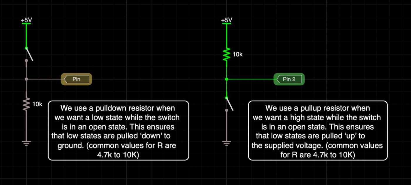
- Button Setup:
- Connect to a GPIO pin.
- Add a pulldown or pull-up resistor for stability.
- (optional) Debounce, IMHO no point on trying to do this with hardware, you can deal with debounce with software, check the links at the end of the post for some debounce options.
The following is the recommended wiring as per the Arduino site.
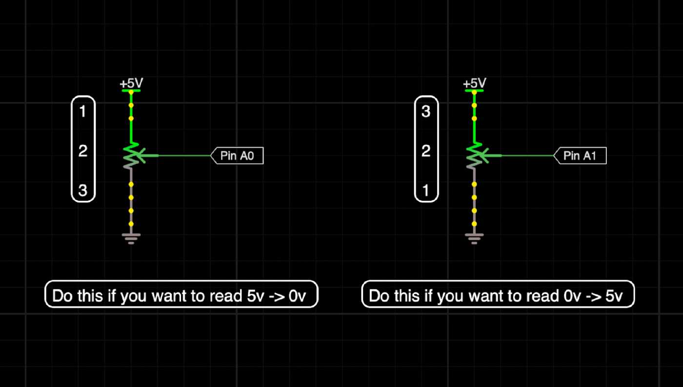
- Potentiometer Setup:
- Connect 5V or 3.3V reference and ground.
- Connect the wiper to a GPIO pin.
- NOTE: If you wire it backwards you can fix it in code by using the map() function so no biggie.
Gate/Trigger Input
- Considerations:
- The eurorack standard or standard-ish… (5V - 10V).
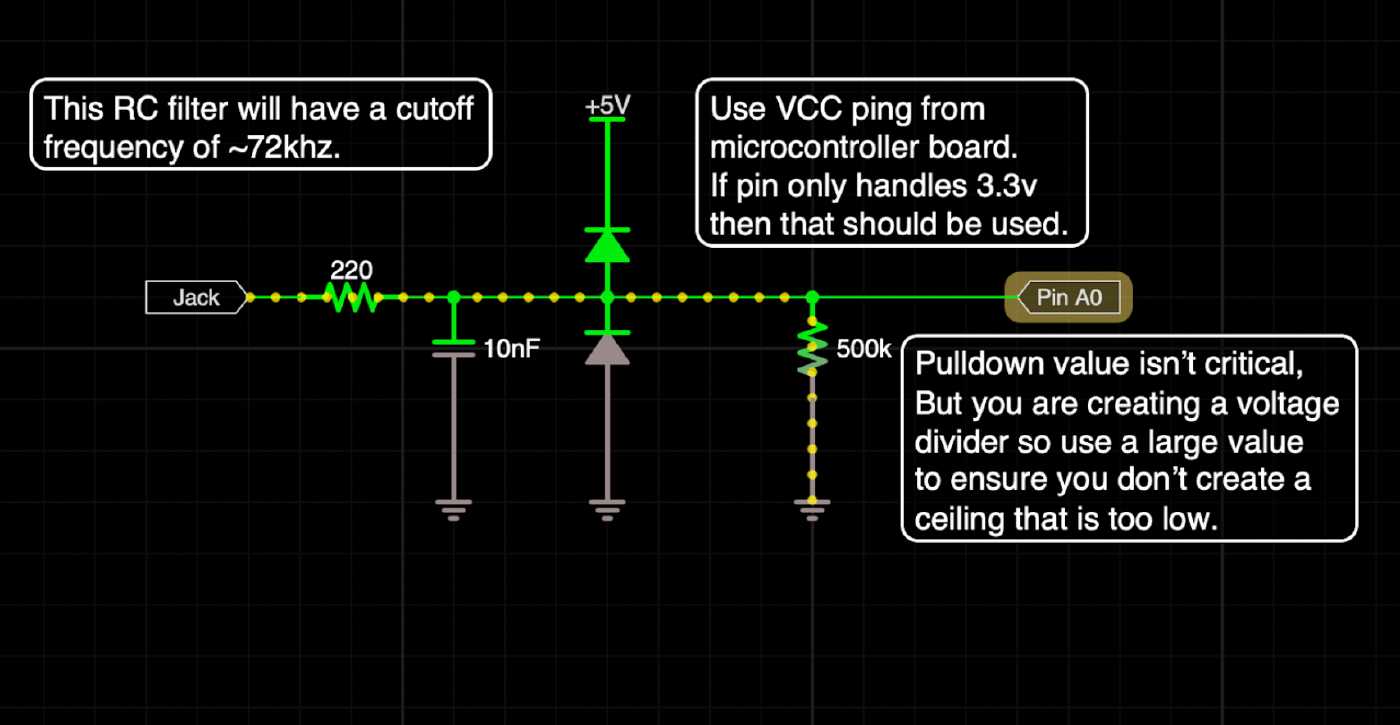
- Use a 5V or 3.3V power pin from the microcontroller for clamping or use a regulated DC voltage.
- Signal path: Input Jack -> RC Filter -> Clamping Diodes -> Pulldown Resistor -> GPIO Pin (Digital or analog pin).
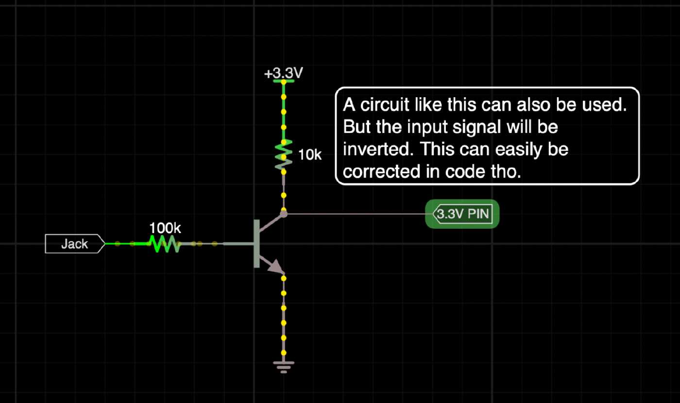
This is an alternative method which uses an inverting buffer. Note that the signal will be inverted.
So why?
RC Filters: The RC Filter will smooth out any unwanted noise that may have been picked up along the way. This is important because we are dealing with microcontrollers which are sensitive to high frequency noise. BTW, other components which process high frequency digital signals are also sensitive to high frequency noise.
Clamping Diodes: These create a hard upper and lower boundary so any voltages outside the allowed ranges will be capped at whatever we set the clamp to. If we have a microcontroller that only accepts 3.3V at the input pin then we would set the upper bound to 3.3V and the lower to ground, thus only allowing voltages from 0 to 3.3V
Pulldown Resistor: This prevents the GPIO input pin from floating when nothing is plugged into the jack and ensures that the pin sees 0V or ground.
Control Voltage Input
- Considerations:
- Scaling voltages for specific applications and microcontroller tolerances
- Use of voltage dividers for scaling.
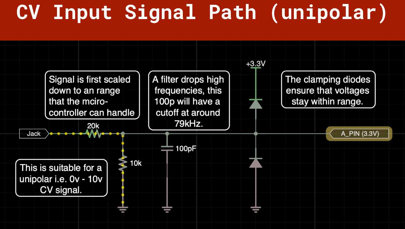
- Signal path: Input Jack -> Voltage Dividier -> RC Filter -> Clamping Diodes -> GPIO Pin (Analog pin).
This example can be used for CV signals that only stay above 0V. That is to say, they do not contain negative voltage signals.
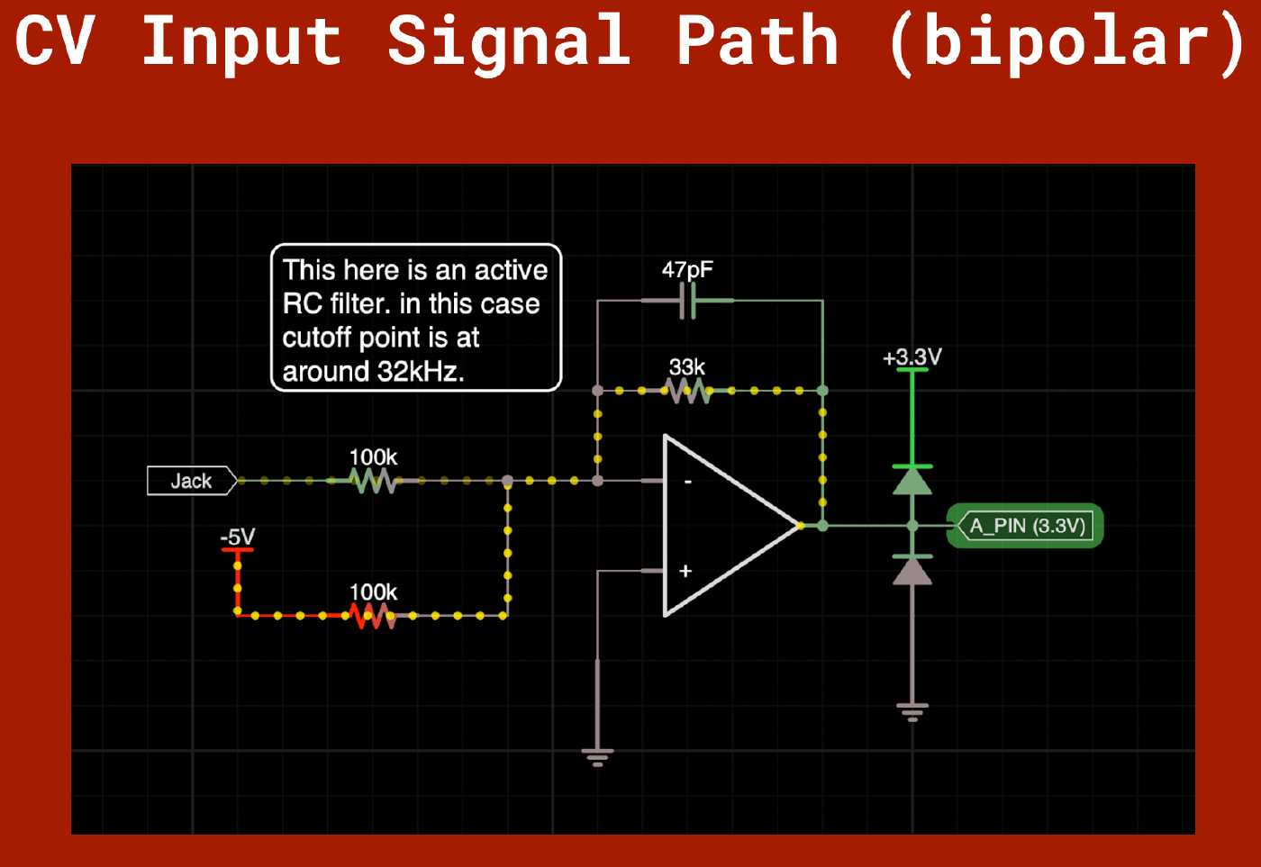
This example can be used for bipolar signals; those that swing from positive to negative, i.e. AC signals.
So Why?
The RC Filter and Clamping Diodes are for protection as explained before. However in this case the RC Filter is also there to reduce the risk of introducing audio aliasing. In audio systems, especially those involving digital processing or conversion, signals above the audible range (typically above 20 kHz) can cause issues due to the sampling process. When a signal is sampled at a frequency lower than twice its highest frequency component (according to Nyquist theorem), frequencies above half the sampling frequency can “fold back” into the audible range, resulting in distortion and artifacts. This phenomenon is known as aliasing.
Another difference here is that we are scaling the signal with a voltage divider which provides us with two things: One, it limits the current of the signal coming so we can work currents within the maximums that can be handled by the microcontroller, and two it scales the signal to that within range supported by the pin. Note that for negative voltages we will first raise the voltage using an offset to make sure it always only swings positive.
BTW, Audio is basically an analog signal much like control voltage, in Eurorack are 10vpp and swing between -+5V. Sounds familiar? well that’s because it is just another AC signal. We can basically do the same, the gotcha has to do with the analog to digital converter (ADC) bit-depth or resolution. Most microcontrollers will have bit depths too low for high fidelity audio. So while we could use them for low fi audio, when it comes to audio we would prefer to use an external ADC IC and wire it using one of the supported protocols. We’ll have a separate chat on this another time.
Conclusion
If there is anything to take away today is that we are ultimately dealing with voltages over time that get interpreted as values in our code. Those signals need to be within the tollerances of the microcontroller so A) Make sure you know them by checking the datasheet. B) Build circuits around those values to ensure that they are with the supported ranges. In a following video we’ll take a look at MIDI as well as take a look at some audio considerations.
Final Thoughts
Today we looked at handling input signals into the micro-contoller. We discussed about the various considerations for tactile controls as well as signals from other modules, and we looked at how to protect our input pins.
Next episode in the series will be about output signals. Until next time, stay creative, stay positive, and handle anything that comes your way in a safe manner.
Additional Resources
[Schematics]( coming soon … )