Microcontrollers: Gate and trigger output signals
Introduction
Hey, friends! Welcome back to our microcontroller adventure. In this episode, we’re diving into the world of output signals. We’ve already explored input considerations, and now it is time to start looking at output signals. Today we will cover gates, triggers and some simple LEDs. If you are wondering what these are: Gates and triggers are control signals used in electronic music to initiate and control events such as note playback, envelope shaping, and rhythmic patterns.
Digital Outputs: Gates, Triggers, and Blinky Things…
Gate and Trigger signals, much like LEDs, basically hold 2 states; LOW, and HIGH. Because of this we can use the same method for driving those types of signals. And that method will be a digitalWrtie()! Of course, there are differences on the hardware side so lets talk about them some.
LEDs
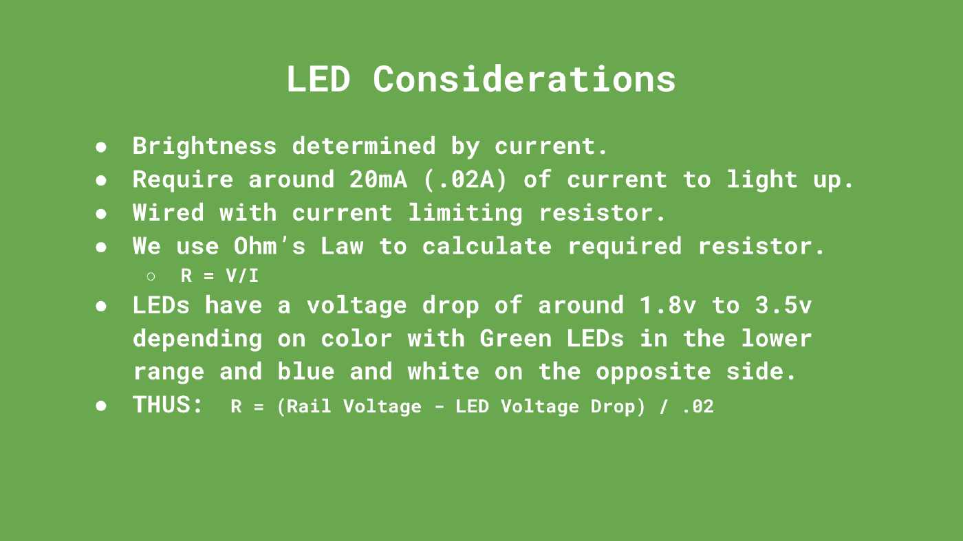
To wire an LED we need a current limiting resistor. LED’s require about 20mA to properly lightup, so we can utilize Ohm’s Law to calculate this, where R = (Vs - Vled) / I. So if we have a 12v rail, and a red LED (with a 1.8 voltage drop) then the equation will work out to be (12v - 1.8v) / .02A = 510ohm. Easy right? One thing to keep in mind is that different color LEDs have different voltage drops, which may affect the result of your calculations. But around 1.8v to 2v is a relatively sane assumption. At the end of the day these don’t have to be accurate, I myself prefer the LEDs to be dimmer than usual so I tend to go for higher value resistors anyway.
Here are some considerations when wiring up LEDs.
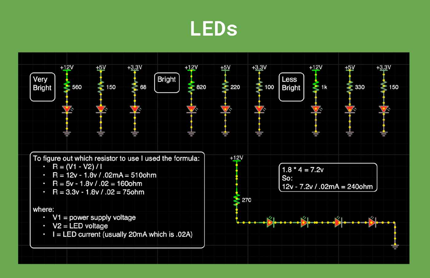
And here is a convenience slide with some commond values we can use:
Gates and Triggers
When wiring up circuits to work with our gate and trigger outputs there are a few things we should consider:
- Voltage Level Shifting: Use level-shifting circuits to convert the lower voltage signals from the microcontroller up to the levels expected by Eurorack modules. For example, scale from 3.3v up to 5v or 10v as needed.
- Signal Conditioning: Implement signal conditioning circuits like voltage clamping, current limiting resistors in order to ensure signals are within expected ranges.
- Buffering: Using buffers or voltage followers can help isolate and protect your Arduino pins by providing a separate current source. This can prevent potential damage from high current or voltage spikes.
- Optical Isolation: In some cases, especially when dealing with sensitive or high-voltage signals, you may want to consider optical isolation techniques. This involves using optocouplers to electrically isolate the input and output sides of your circuit, providing an extra layer of protection against voltage spikes and noise. Tho this teqchique is rarely found in gate and trigger outputs in Eurorack modules. It is however part of the MIDI standard, but we’ll cover MIDI in a future post.
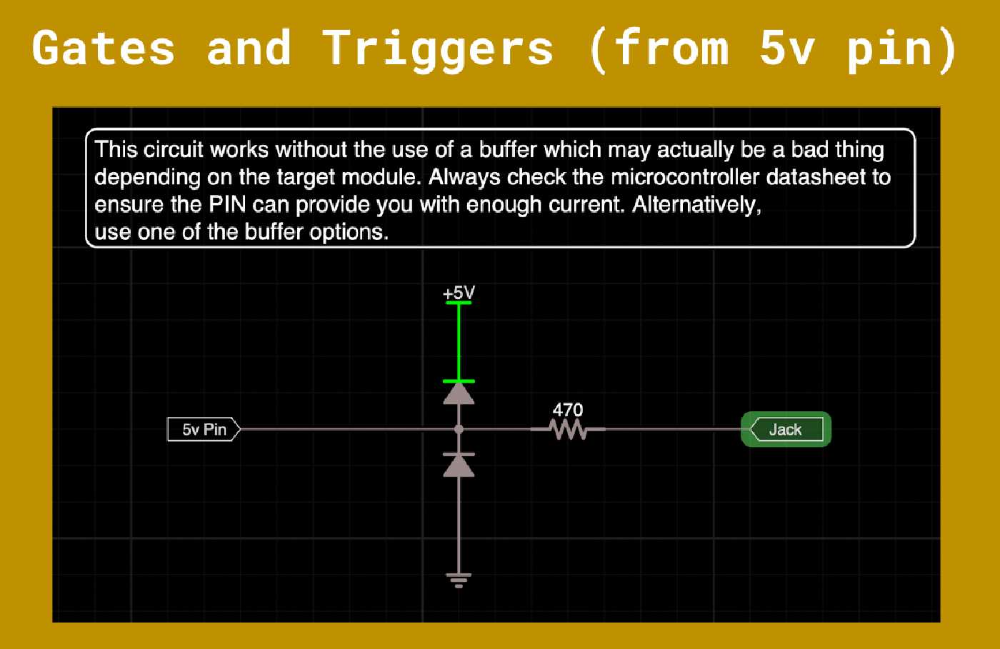
Here are some examples showing how to wire a gate/trigger output. This first example assumes you have a microcontroller capable of sourcing 5v at each pin. Do keep in mind that you will be limited by how much current each pin is capable of driving which may not be much at all.
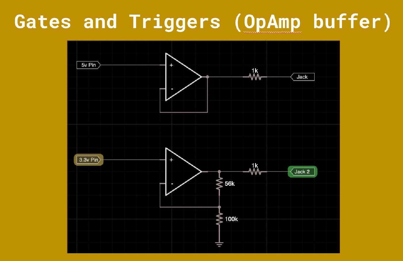
Here is a better method involving an opamp buffer. It can be done with a non-inverting amplifier if you need to scale the signal too. The benefit here is that since the opamp can sync and source current our microcontroller pin is isolated from the output jack. Allowing the jack to source current from the opamp rails!!! Bonus!
In this last example here we wee an alternate approach. You may consider doing this if you only have a single output as this is achieavable with a single transistor and a resistor or two.
And that is all there is to it!
The Code
To generate digital signals from our pins we will need to do the following:
- Configure the PIN as a digital output pin.
pinMode(PIN_NO, OUTPUT); - Use digital write to set the state as HIGH or LOW.
digitalWrite(PIN_NO, HIGH);
For example, the following code will toggle the state of the LEDs and Gate every 5 seconds:
#include <Arduino.h>

unsigned long lastBlinkTime = 0;
const int blinkInterval = 5000; // blink interval in milliseconds

void setup() {
  // Configure the pin as OUTPUTs
  pinMode(PB12, OUTPUT);
  pinMode(PB13, OUTPUT);
  pinMode(PA11, OUTPUT);
}

void loop() {
  unsigned long currentMillis = millis();
  if (currentMillis - lastBlinkTime >= blinkInterval) {
    lastBlinkTime = currentMillis;

    // Set the new state of the pin to be the oppostite of the current..
    digitalWrite(PB12, !digitalRead(PB12));
    digitalWrite(PB13, !digitalRead(PB13));
    digitalWrite(PA11, !digitalRead(PA11));
  }
}
Conclusion
Today we explored driving gate and trigger from our microcontrollers, and we discovered that they are actually quite easy to configure. In the upcoming videos we will start taking some of the knowledge we have accumulated and buld some fun projects so be sure to check back. And if you haven’t already be sure to subscribe to the YouTube channel so you can be the first to know when thye are out!