When Not Fixing a Bug Is the Right Path
Short version: we investigated a faint audio pop in a specific filter sweep scenario, tried a narrowly scoped DSP change, found it caused audible regressions on constrained targets, and concluded the right follow-up is an architectural design spike — not a quick patch.
Why this matters (TL;DR for busy readers)
- We did the investigation the right way: reproduce first, measure, hypothesize, change, and measure again.
- When a partial fix regresses real users (or MCU targets), it’s better to roll back, document what we learned, and plan a proper architecture change.
- This post shows how to run that exact process in a compact, beginner-friendly way.
Problem (sanitized)
A faint but audible click occasionally appeared during fast filter sweeps when only the low band was audible and the filter crossed center rapidly. It was rare and hard to reproduce by hand, so we insisted on building a reliable, automated replay and measurement surface before changing the DSP.
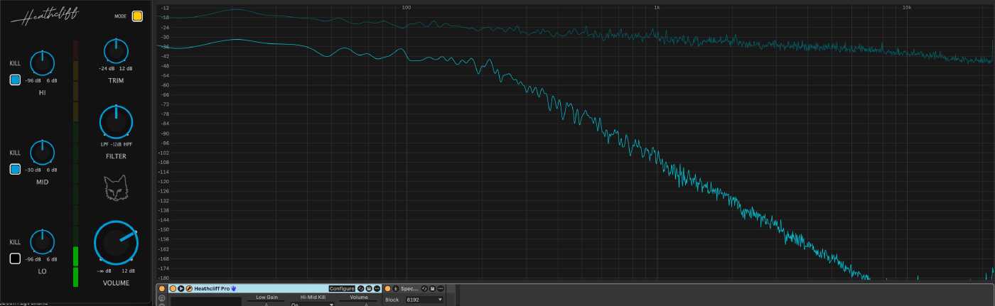
Baseline posture: low-only signal before the aggressive sweep.
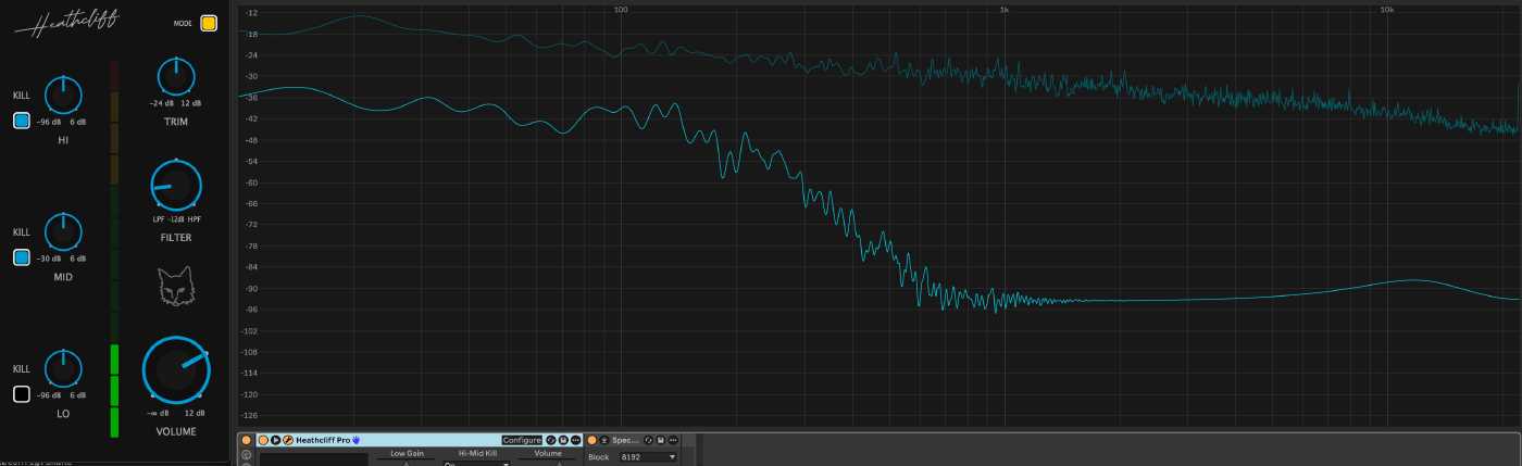
Example capture showing the stronger transient we called the “pop” (anonymized).
What we wanted to learn
- Can we reproduce the symptom deterministically? (If not: don’t code.)
- Which code boundary owns the effect (app orchestration vs. shared DSP library)?
- Can a minimal change eliminate the pop without regressions, especially on microcontroller-class targets?
How we approached it (short checklist)
- Narrow the replay contract: LOW-only audible posture + bass-heavy input + repeated fast center crossings.
- Add deterministic probes: seeded pink-noise input + perf stress harness with multiple block sizes.
- Add a frozen baseline: hold the dial at center to measure the signal floor.
- Capture seam windows and metrics (lightweight, audio-thread-safe CSV dump).
- Hypothesize a minimal DSP mitigation and test it behind a feature flag.
- Evaluate results and rollback if the mitigation regresses behavior or runtime cost.
Short version of the experiments
- Frozen baseline showed a non-zero signal floor (expected for near-transparent filters). This told us how low a real fix could hope to go.
- A scoped sub-block smoothing change (advance filter smoothing more often, inside a block) reduced crossfade-zone jumps numerically but produced audible regressions when applied naively across the crossfade path.
- A scoped sub-block smoothing change (advance filter smoothing more often, inside a block) reduced crossfade-zone jumps numerically but produced audible regressions when applied naively across the crossfade path.
- We did not validate this mitigation on MCU targets. While the audible regressions were observed on our desktop builds, the added per-subinterval work also risks exceeding realtime budgets on MCU-class hardware and causing missed deadlines or audio dropouts. Any DSP mitigation must therefore consider target realtime constraints before shipping.
What we tried that didn’t work
- Per-block smoothing — reduced some metric-level discontinuities but did not remove the boundary-style events.
- Sub-block coefficient updates — reduced numerical crossfade jumps but introduced audible micro-discontinuities at sub-interval seams.
- Aggressive smoothing — masked the symptom in some runs but hurt responsiveness and tuning precision.
Pseudo-code (sanitized, beginner-friendly)
// Pseudo C++ (conceptual, sanitized)
// This illustrates the idea: advance the smoother per-subinterval
// when a crossfade is active, otherwise advance once per full block.
void processBlock(float* buffer, int numSamples)
{
  if (isCrossfadeActive())
  {
    const int subSize = 32; // example sub-interval size
    for (int offset = 0; offset < numSamples; offset += subSize)
    {
      int thisSize = std::min(subSize, numSamples - offset);
      advanceSmoother(thisSize);    // move coefficient smoothers forward
      refreshCoefficients();        // recompute biquad coefficients
      processSamples(buffer + offset, thisSize);
    }
  }
  else
  {
    advanceSmoother(numSamples);
    refreshCoefficients();
    processSamples(buffer, numSamples);
  }
}
This looks reasonable at first glance, but each coefficient refresh can change how the filter state maps to the delay buffers, which can produce small discontinuities at interval seams.
Why the sub-block idea failed here (simple explanation)
Root cause: per-block coefficient updates create state discontinuities in time-varying IIR filters, and those discontinuities become audible when exposed by crossfade blending.
IIR filters (biquads) hold internal delay-line state that depends on past samples. Each coefficient update changes how that state is interpreted. Performing multiple coefficient updates per block doesn’t smooth the transition — it creates multiple small discontinuities at the sub-interval seams. When the output is partially wet by a crossfade, those discontinuities are directly audible, producing clicks rather than smoother results.
We did not validate this mitigation on MCU targets. While the audible regressions were observed on our desktop builds, adding frequent sub-block computations also risks exceeding realtime budgets on MCU-class hardware and causing missed deadlines or audio dropouts. Any DSP mitigation must therefore consider target realtime constraints before shipping.
Data highlights (anonymized)
| Probe (example) | Before (worst crossfade) | Frozen baseline |
|---|---|---|
| boundary_jump (block 64) | 0.09 | 0.05 |
| boundary_jump (block 512) | 0.07 | 0.057 |
Interpretation: the frozen baseline is the signal floor from near-transparent filtering; a real mitigation should move the sweep tests closer to that floor, not necessarily to zero.
Sanitized probe (example)
I’ve included a small, sanitized snippet from the perf probes we ran. The raw capture CSVs live in local debug captures and are not committed; the file below is an anonymized summary suitable for the post.
Snippet (selected rows):
| blockSize | frozen_baseline | host_path_before | applied_transition_peak | host_path_after_patch |
|---|---|---|---|---|
| 64 | 0.0529 | 0.0874 | 0.0030 | 0.0872 |
| 128 | 0.0565 | 0.0999 | 0.0051 | 0.0996 |
Interpretation: the frozen baseline column shows the signal floor; the large host-path numbers are the aggressive worst events surfaced in the perf harness. The applied_transition_peak column isolates the deferred center-reset seam and is much smaller — this helped narrow the root cause.
Key takeaways for beginner devs
- Repro first: if you can’t reproduce reliably, you’ll likely waste time chasing illusions.
- Measure and baseline: add a frozen or control scenario to understand the signal floor.
- Prototype small, behind a toggle: keep changes reversible and gated.
- Rollback is a feature: if a fix regresses, roll back, document what failed, and record why.
- Think about runtime targets early: what runs fine on a workstation may not on an MCU.
After a long day of testing and tinkering, it’s tempting to force a quick fix just to feel progress — resisting that urge and following the evidence mattered here.
Why architecture is the right next step
This is not a tweak — it’s a different class of solution. Short-term patches are likely to fail; the correct fixes are architectural and require changing how filter state and parameter updates are handled across time. Candidate solution classes include:
- Continuous coefficient morphing — evolve coefficients per-sample or with a per-sample morphing strategy so the filter’s internal state is never reinterpreted abruptly.
- Topology-preserving filter designs — choose filter topologies or state representations that remain valid as parameters change, avoiding state reinterpretation jumps.
- Dual-filter crossfade with state alignment — run two matched filter instances and reconcile their internal states before performing the crossfade so the blend never exposes a discontinuity.
Each of these options represents a design boundary change and should be prototyped and validated with platform-specific budgets (especially MCU-class targets) before committing to a shipping fix.
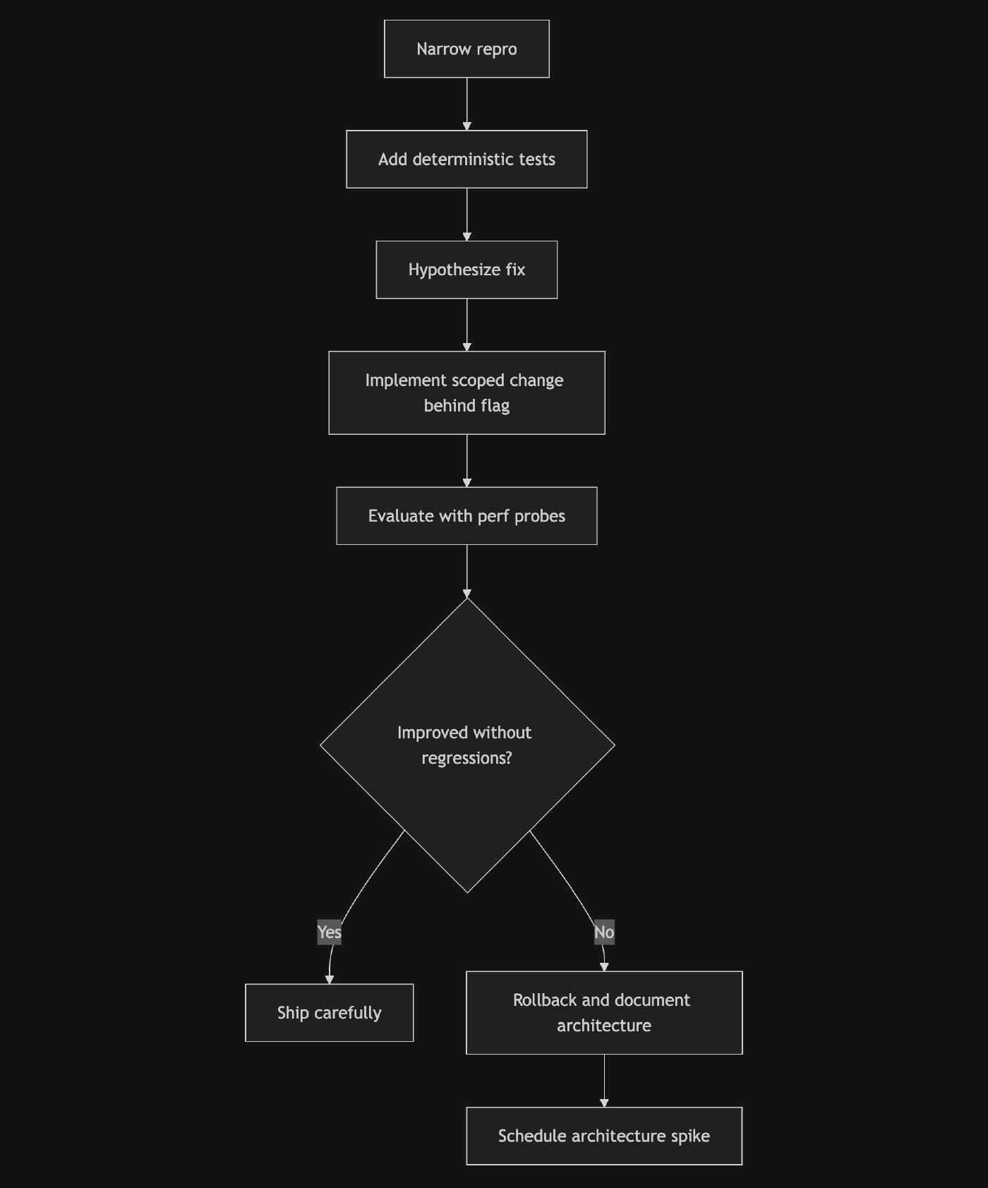
Simple repro-debug flow
Practical next steps (what we recorded)
- Keep the deterministic probes and frozen baseline in the test suite.
- File a short architecture spike to explore continuous coefficient morphing or alternative topologies (MCU budget analysis included).
- The investigation also left us with a stronger DSP toolchain and better debugging tools, which make future cross-repo DSP iteration and diagnosis much easier.
Final note
Not fixing a bug immediately isn’t quitting — it’s disciplined engineering. We chased evidence, tried a surgical mitigation, observed regressions on real targets, rolled it back, and now have a clear, data-driven architecture path forward. That’s a win worth writing down.