Dual ADSR / VCA Combo - Part 2: Build Journey and Retrospective
Introduction
Hey, what’s up? Juan here, and we’re diving into the second part of our Dual ADSR/VCA combo module. If you missed the first part, check this link for a recap. Today, we’re not just wrapping up the project; we’re reflecting on the journey.
Build Highlights
Alright, let’s kick things off with a speedy recap. As you recall we combined an ADSR circuit together with a VCA circuit so that we can run audio and a gate signal in order to shape the audio signal coming out of the module. But we didn’t stop there, we also added additional inputs for CV to allow for both 5v and 10v input ranges. We also added an inverted envelope output with a switchable range.
For this project I wanted to test a few things differently:
- The first thing was using some slider potentiometers I found on Aliexpress. They were not standard so I had to create custom footprints in KiCAD form them.
- Normally when I create front panels I use shapes for the hole cutouts where the components feed through. However, I find re-doing the same work moedule after module so this time I decided to make footprints for those front-panel holes. I had already done something like this for the mounting holes and was very happy with those results so figured this would save us time in future modules.
- Added a test point for setting up the 5v reference needed for the inverted envelope.
- Decided to arrange the sheets so I could keep the two circuits separated in order to have fewer components on each individual sheet.
Upon receiving the parts, I created the main board, control board, and front panel on KiCad. This included newly created footprints. Then, I sent them off to manufacture.
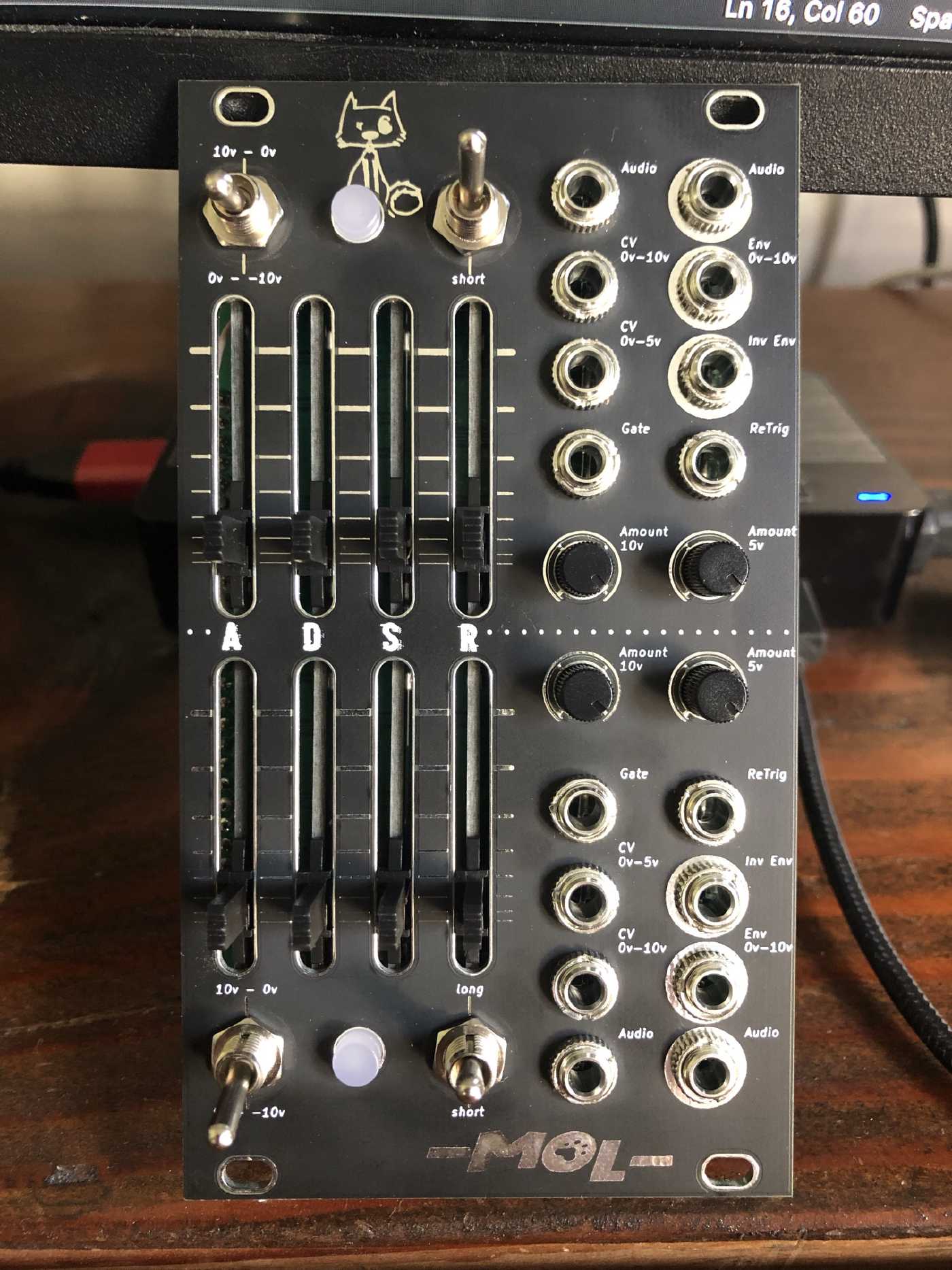
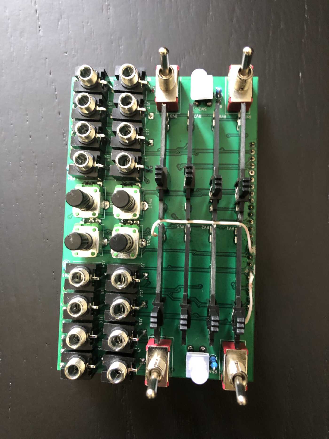
Building the module wasn’t all that simple. Those new sliders turned out to be a bit of a challenge to place on the board and ended up taking WAY longer than other front panels I’ve done in the past. Eventually I got it all built, but it wasn’t all smooth sailing though. Here is a look at the finished product!
Issue Resolution
Now, let’s talk problem-solving. Here’s a quick rundown of the hurdles we faced:
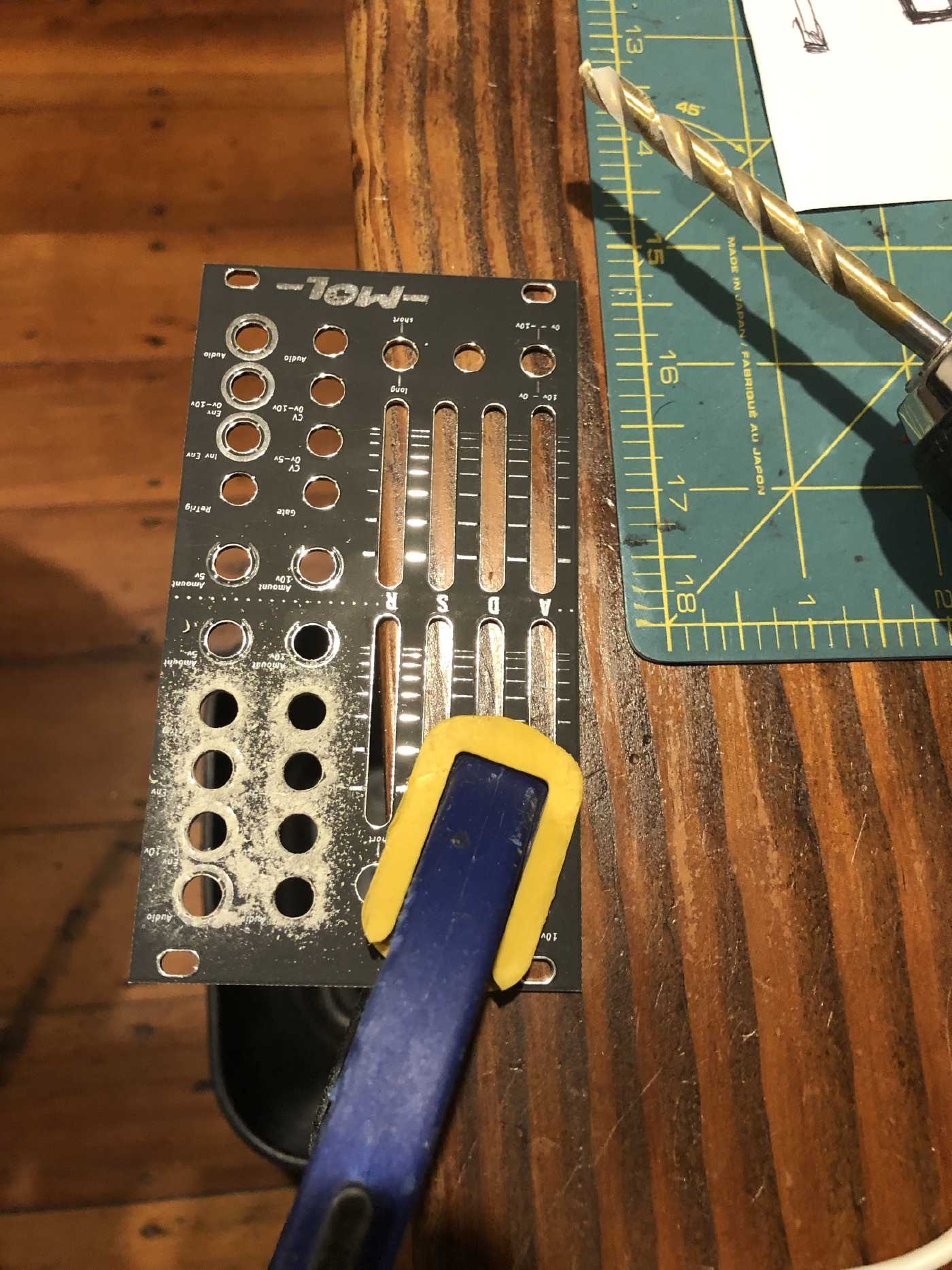
- Solder mask causing small holes for jacks, I had to drill them to make the holes bigger. This was not a big deal since this PCB is all cosmetic and the nuts on those jacks would cover any imperfections made by drilling.
- LED pin puzzle with push buttons! Turns out the buttons I had obtained from Aliexpress had the pins reversed in the description/datasheet. On the site it showed as the anode having the long leg, but in reality it was the cathode that had the long leg. I ended up having to sacrifice two switches, since de-soldering them ended up in destruction of the buttons. I had extras tho so no biggie.
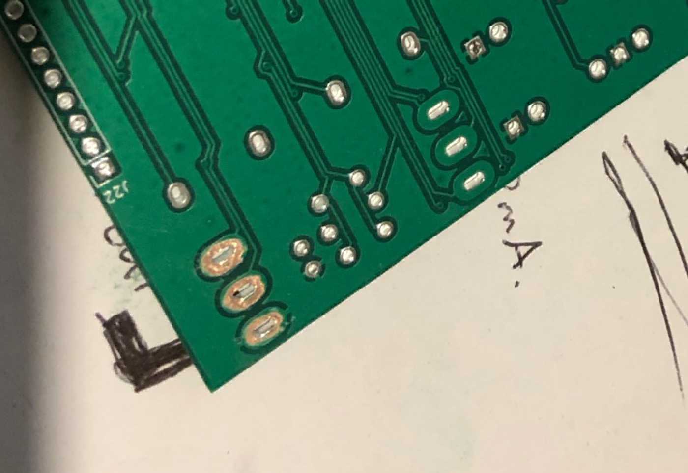
- Connector mix-up causing ADSR issues. This one sure caused me grief, I probably spent a good 3 days troubleshooting and coming out with a good solution. Once I found the schematic was wrong, I was afraid I was going to have to re-order the boards, but once I fully understood root cause I was able to find a solution that allowed me to save the board by cutting some traces and re-routing the track with some jumper wires.
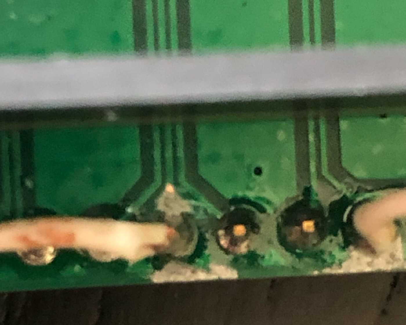
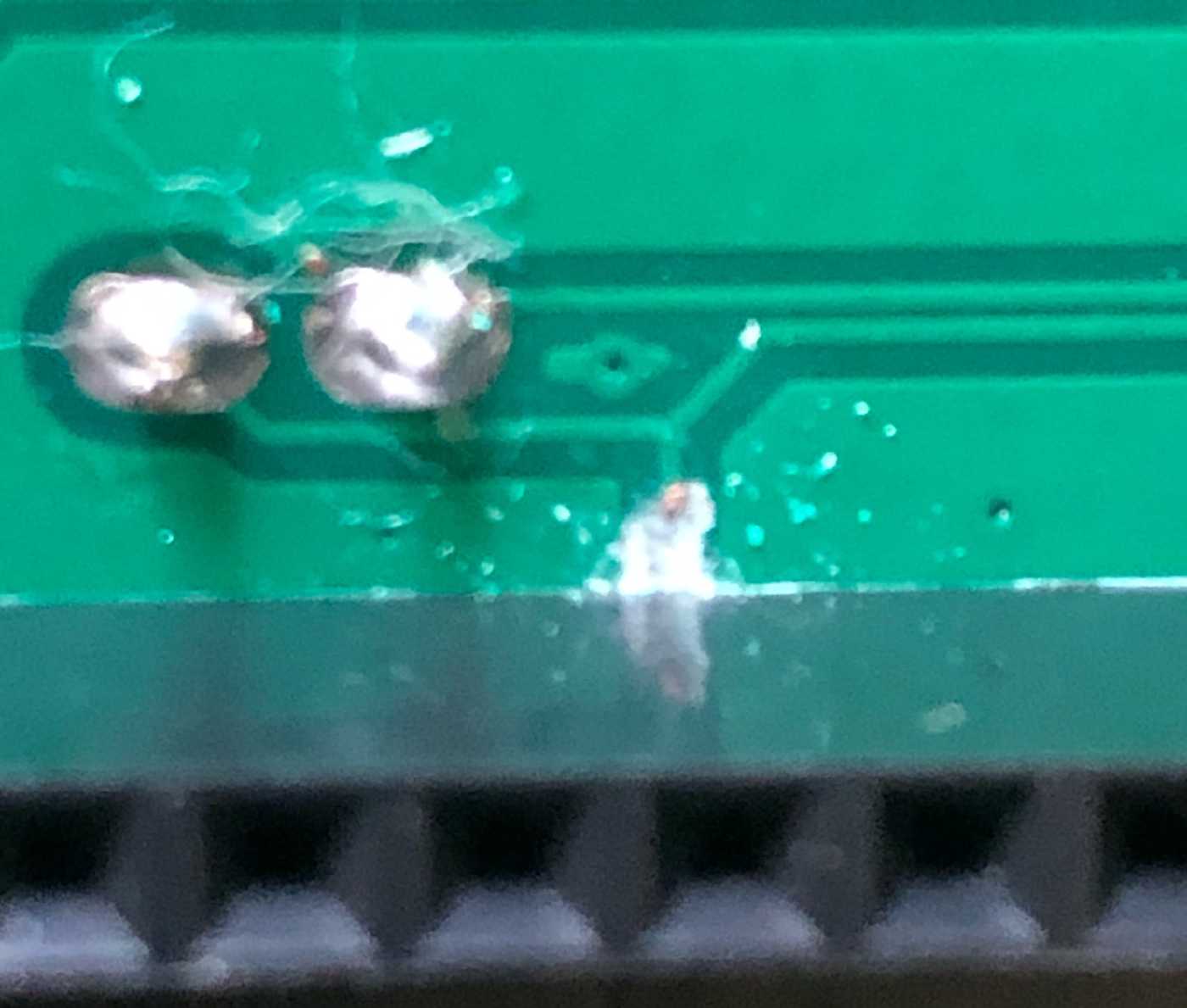
- Pad-less footprint. I used a footprint I found on the web for the switches and it turned out that the footprint was bad and did not expose the copper. So I had to scrape them to be able to get the switches soldered on the board.
Design Reflection
Now, let’s reflect.
On the slide potentiometers. I really do like the idea behind them. They have the resistive track exposed which is odd, but because how they are mounted it means the are less likely to crackle due to dust. At least that is my theory, time will tell. They are little too tall, I tried to compensate by allowing some of the casing on the slide thrugh the panel opening and that worked out rather well. On the cons side though, they are quite dificult to place. In fact compared to most common slide potentiometers they are significally more dificult, this alone is probably enough to make me not want to use them again. Though, I will say after building a the 3rd board this was a little bit easier.
Using footprints for the holes on the front panel is definately the way to go! Even though I had issues with the sizing, this turned out to be a really good move on my part and I can certainly see this resulting in many hours of saved time in the future.
The test point was a great idea, but I really need to make sure to add a ground test point too next time.
Lastly, the idea to split the project the way I did was good in theory but poorly executed. I’m not giving up on this idea tho, I do think this is a good way to keep things organized and simple. But I think next time I’ll take a slightly different approach to how I break out the functional blocks.
Calibration and Testing
If you decide to build this module here is how you’d calibrate it.
Using a multimeter connect comm to ground and the probe to the TP1 (5v). Then using a screwdriver adjust Ref_Adj until it reads exactly 5v.
Next you’ll need to adjust the offset for each of the envelopes. This calibration is best done with an oscilloscope but can also be done by ear here is how:
a. OSCILLOSCOPE METHOD: Connect the Env output jack to an oscilloscope. (this is the jack labeled Env 0v-10v) Using a screwdriver the Offset trim pot until it is 0v or just a few milivols less. The offset is injecting a negative voltage to ensure that no audio bleeds through, but 0v is a good starting point. You’ll probably want to send an audio signal to the audio input, I used a triangle from an oscillator which I know was 10v peak to peak, then used a nother channel on the oscilloscope to examine the audio ouput adjusting until no audio was bleeting through.
b. BY EAR METHOD: If you don’t have an oscilloscope, you could simply use a multi-meter on the env output. But you really don’t need it. Just turn the ajust clockwise all the way. Then plug in an audio signal to the audio input jack and plug the output jack to a mixer so that you ucan hear the output. Adjust until you don’t hear anything, and test.
Closing Thoughts
And there you have it, the Dual VCA/ADSR module journey from start to finish. By the way, I’ve named the module Meow Out Loud (MOL). Huge thanks for being part of this ride. Stay tuned for the next project. Until then, keep creating and making some awesome tunes.
Resources
Project Files: Scruffy Cat Github Page
Our Sponsor: https://www.pcbway.com/
Part 1 of this project series: https://scruffycatstudios.com/posts/degvca/
LED Switches used: TS-H002 Touch Switch Pin With Light
Slide Pots: 40MM Straight Slide Fader Exposed Sliding Potentiometer Single B50K Slide Stroke 28MM
Trim Pots: I got mine at a surplus store and was not able to find them online. Here are some alternatives. These types of trim pots are called “open carbon type”. Here are some examples.